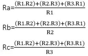
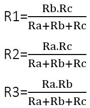
This Pi Attenuator Convertor is designed for RF engineers and electronics enthusiasts to quickly calculate the resistor values needed for a Pi-type attenuator based on desired attenuation and system impedance.
Conversion Formula
R1 (shunt) = Z₀ × (K + 1) / (K – 1)
R2 (series) = Z₀ × (K² – 1) / (2 × K)
where K = 10^(A / 20), A = attenuation in dB, Z₀ = system impedance in ohms
How the Formula Works
The formula uses the voltage ratio K derived from the specified attenuation in dB. R1 is the shunt resistor, and R2 is the series resistor. These formulas ensure the attenuator maintains the desired system impedance while achieving the target attenuation.

Example Calculation
If you want an attenuation of 10 dB for a 50 Ω system:
K = 10^(10 / 20) ≈ 3.1623
R1 = 50 × (3.1623 + 1) / (3.1623 – 1) ≈ 86.60 Ω
R2 = 50 × (3.1623² – 1) / (2 × 3.1623) ≈ 60.36 Ω
Why use this Pi Attenuator Convertor:
1. Quickly determines resistor values for RF attenuator design.
2. Eliminates manual calculation errors in RF circuits.
3. Helps maintain correct impedance matching in signal paths.
4. Saves time for engineers during prototyping and testing.
5. Useful tool for students and hobbyists learning RF circuit design.


