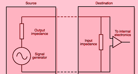
circuit has low output impedance and high input impedance.
The circuit usually has a high input impedance when it is driven by the voltage requirement whereas the low output impedance means that it must provide a larger current. This is a good thing for the input voltage, as if the input impedance is high compared to the impedance source then the voltage level will not drop too much due to the divisor effect.
For example if you want to amplify the signal voltage, it will be necessary that you get the proper input voltage at your amplifier input. in this case, if your amplifier has a high input impedance then the voltage will not drop on its input and thus your input voltage is maintained at the desired level. However, if your amplifier has a less input impedance then it can happen that the voltage drop occurs at the input and thus you end up getting a smaller voltage value on the input consequently amplifying the wrong signal.
Low output impedance is desired to suck the maximum current from the circuit.High impedance means the circuit draws or gives little power to the signal. low impedance means the circuit draws or gives more power to the signal.
It is generally a good idea to follow the rule that the circuit must have high input impedance (so it can interact properly with other circuits that may or may not provide enough power) and low output impedance (so that the circuit can interact properly with others, which draws a lot of input power).
This may not always be possible. for example, given thermocouple circuit. the output of the circuit is limited by the physics involved in the thermocouple process.As long as the output impedance of the signal is lower than the input impedance of the circuit the signal is entering, everything works fine.
If you look at the case of an audio amplifier, you might see line level inputs with 10k ohm impedance where the source is probably 100 ohms. this makes the analysis simpler and makes the signal level less dependent on the proper input impedance of the next stage.
But for the microphone, it depends. a piezo mic may require a 50k input impedance to get closer to the microphone impedance. but a 600 ohm microphone requires a 600 ohm impedance input on the preamplifier. in both cases, improper matching will cause the frequency response and sensitivity to be compromised.
And the output to the speakers may be only 0.5 ohm impedance where the speaker itself is 8 ohms. this is in part because it is a more stable configuration, because the speaker is a complex impedance, a resistive, capacitive, and inductive load mix that changes its composition with frequency.
In low to medium speed logic circuits, you want the output impedance from the logic gate to be low and the input impedance to be high so that 1. the connecting gate does not load the output down in such a way that it no longer shows a clear or low altitude and 2. You can connect some input to a single output.
But in high speed logic, you want the input impedance to adjust the output impedance. this is not necessarily for maximum power transfer, but to prevent standing waves. the standing wave is a reflection of the electrical signal back to the line. they occur when the output impedance, lines, and inputs do not match.
This is especially true for RF (radio) signals. TV antenna has a matching transformer to match 300 ohm impedance from antenna to 75 ohm coax, then input of your TV has a 75 ohm impedance. if this is not true, you will get reflection of standing wave and loss of signal. if we are still using analog TV, you may see strange ghost effect if coax from antenna is very long.
sometimes you want high input and low output impedance, sometimes you want the impedance to be matched.

